We conducted some experiment to de-clutter the diagrams and especially the overview diagram showing all the sub-diagrams on one view.
Here is the original (obfuscated) diagram.

After several trials, we chose the following rules

Zoom on one sub diagram :
Original
 Modified

As package (sub-diagram) inter-connections are presented inside each sub-diagram, one idea could be that the solution generate first an overview of how the packages are connected.
Example

and then generate one picture/page per sub-diagram. In our opinion this splitting from overview to more detailed view would follow the pedagogic way of explaining the system to someone new to it.
We are awaiting feedback on this idea(s) and we are now exploring an additional way of abstracting the diagram by grouping elements by names.
We also asked our supervisor, as only they, are experts in the system, if he had tips on generic rules which could dictate which components are important to show and which can be remove without altering the message they want to present with the diagrams. Awaiting for answer.
Here is the original (obfuscated) diagram.

After several trials, we chose the following rules
- Component objects are represented with “C” whereas interfaces with “I” (this is not ‘pretty’ but it helps us differentiate them while we are still playing around with ideas)
- We only show connections within a package. No more crossing lines from inside a package to another.
- Interfaces which are not connected to anything are listed in the upper part of their ‘home’ components
- Interfaces having other connections than the one linking them to their ‘home component’ are detached from the component (The “I” component objects). We still show to which component they belong to by drawing a line ‘home component’-> interface
- All connections crossing from a package to another package are listed under the corresponding connected components or interfaces. With the form <PackageName>.<ComponentOrInterface>().

Zoom on one sub diagram :
Original

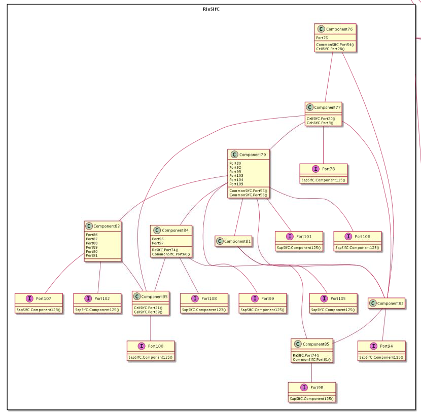
Discussion
As we can see, grouping elements in that way lightened the diagram while preserving the original information.As package (sub-diagram) inter-connections are presented inside each sub-diagram, one idea could be that the solution generate first an overview of how the packages are connected.
Example

and then generate one picture/page per sub-diagram. In our opinion this splitting from overview to more detailed view would follow the pedagogic way of explaining the system to someone new to it.
We are awaiting feedback on this idea(s) and we are now exploring an additional way of abstracting the diagram by grouping elements by names.
We also asked our supervisor, as only they, are experts in the system, if he had tips on generic rules which could dictate which components are important to show and which can be remove without altering the message they want to present with the diagrams. Awaiting for answer.


